Hey there! When it comes to our computers, think of motherboards as the brains, the central hub that links and coordinates all the different parts to make sure everything runs smoothly. Now, let’s talk about a specific superhero on the motherboard – the JFP1 header. It’s like the bridge that connects the motherboard to the front panel of our computer case.
So, what’s the JFP1 all about? Well, it goes by a few names like Front Panel Header or Front Panel Connector. Picture it as the friendly mediator between the motherboard and the cool stuff on the front panel – you know, buttons, LEDs, and audio ports. Its job is to create this neat and organized connection, letting us easily interact with our computer.
Understanding how the JFP1 header works and getting it installed correctly is pretty crucial for anyone building or maintaining a computer. From firing up the system to plugging into audio ports, the JFP1 header is like the unsung hero making it all happen and giving us those handy visual cues.
Now, in this guide, we’re going to dig into why the JFP1 header is a big deal, check out its pin setup, and figure out why getting the polarity right when connecting front panel components is so important.
Whether you’re taking your first dive into computer assembly or just want a quick refresh, this guide has your back, giving you the lowdown on installing and connecting that JFP1 header like a pro.
What Is JFP1 On Motherboard?
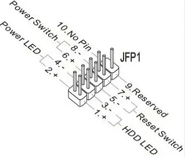
JFP1 stands for “Jumper Front Panel 1”. As you may have inferred from the name, it is a motherboard header to set up the front panel’s power, reset, and speaker connections.
JFP1 connectors’ pinouts must be appropriately set up to function with the motherboard’s front panel pins. The external cables that connect to them have distinct pinout markings that should match those provided by JFP1.
When setting up a new PC or upgrading an old configuration, polarity is another crucial element in obtaining the proper connections from JFP1. The plastic shroud around the connector can occasionally cause problems when connecting front panel components. If this occurs, removing the item may provide relief since its height prevents connection points from reaching their specific headers on the PCB board.
What Is The Role of JFP1? Top 6 Purposes
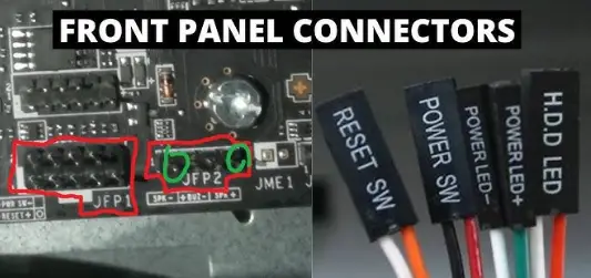
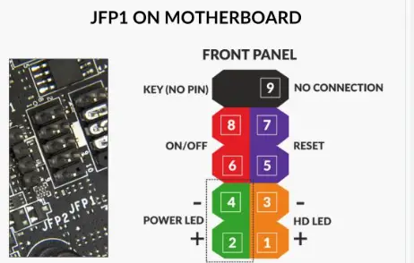
The JFP1 (Front Panel Header) on a motherboard works as a connecting point for the various parts of the front panel of the computer casing. The motherboard can connect with and manage the front panel buttons, LEDs, and audio ports, thanks to the JFP1 header. The leading roles of the JFP1 header pins are listed below.
- Power Button: The power button pin lets you turn the computer on or off by depressing the power button on the case’s front panel.
- Reset Button: The computer may be reset by pressing the reset button on the front panel, thanks to the reset button pin.
- Power LED: The power LED pins are connected to the front-panel power indicator light, which shows whether the computer is on or off.
- HDD LED: The pins of the HDD LED are connected to the front-panel hard drive activity indicator light, which flashes or blinks to indicate when the hard drive is being accessed.
- Power Button LED: A power button LED is an optional LED light that may be connected to the power button LED pins to turn on when the computer is turned on.
- Speaker: Some motherboards could contain a speaker pin on the JFP1 header. This pin is intended to connect a system speaker that emits audible beep codes during boot-up for debugging purposes.
Different motherboards may have a different JFP1 header layout and pin configuration.
Where is JFP1 on a Motherboard?
The position of the JFP1 header on a motherboard varies depending on the motherboard model. The JFP1 header is typically located along the motherboard’s edge, next to the bottom or side.
You can consult the motherboard manual or the paperwork that came with your motherboard to find the JFP1 header on your motherboard. A thorough diagram or description of the motherboard layout in the documentation will generally show the JFP1 header’s position.
If you don’t have access to the motherboard manual, try spotting the JFP1 header on the motherboard by looking for a collection of tiny connectors or pins.
The labels on the pins or other markings usually indicate their purpose. On the motherboard, search for symbols like “JFP1,” “Front Panel,” or “FP.”
To avoid damage, take care while connecting components to the JFP1 header. Ask for help from an expert or contact the motherboard manufacturer’s support if you are unsure or uncomfortable with the procedure.
The failure of the power button, reset button, sleep mode issue, or even system boot failure owing to faulty connections might result from skipping this important step, none of which are quick or simple to diagnose, let alone remedy.
In other words, when designing your computer, matching the JFP1 pinouts correctly is one of the most crucial stages! Each header has a set of pins that are either meant to be connected concurrently or are meant to be connected left to right (for power and reset switches).
In addition, they have obvious (+) and (-) labels if you’re connecting LED lights, so be sure to pay special attention to where each one goes.
Do Front Panel Connectors Accept Any Pin?
No, not at all. It is crucial to match the pinouts of the cables from your case’s front panel and the JFP1 connection on your motherboard before installing front panel connectors.
Each of the crucial pins mentioned above requires a certain connection to work correctly, and polarity errors could result in electrical current flowing in the wrong directions.
A unique orientation about polarity (+) and (-) is required when connecting LEDs. Therefore, pay great attention to this.
When configuring your setup, refer to the layout described in the documentation with your motherboard because it will show you which pins should line up with specific cables.
The peace of mind that comes from double-checking connections rather than shoving cables in places where they might not fit correctly and cause unintended problems with expensive repercussions comes from connecting each cable properly.
What Are The Split Connectors For (+) And (-)?
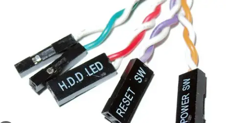
It can be challenging to connect the front panel connections to JFP1, but a crucial first step is comprehending the distinction between (+) and (-) split connectors on LED wires.
When connecting LED pins to JFP1, you’ll typically discover that each wire has two independent pins on the other end and one with a red or black line indicating the positive pin.
Before turning on your computer, double-check that all your wires are correctly connected if you need clarification.
Mismatching not only has the potential to harm your system seriously, but it can also make some motherboard components inoperable until reset with particular jumper switches.
Choose equally divided polarized connection pairs when purchasing lights for computer case mods or other applications. This will make the process easier because the cords are marked out, making mistakes less likely.
Is it necessary to use polarity while attaching JFP1?
When dealing with the JFP1, or Front Panel Header, on my motherboard, it’s crucial to get the polarity right, especially when tinkering with LEDs. Polarity here refers to making sure I align the positive (+) and negative (-) connections properly when hooking up various components.
The power LED, HDD LED, and power button LED usually come with handy polarity indicators or markings. These little clues help me position the positive and negative connections exactly where they should be on the pins of the JFP1 header.
Now, here’s the thing – if I mess up the polarity or connect things the wrong way, the front panel components might act up or not light up at all. Take the power LED, for example; if I mix up the positive and negative terminals, it might decide to stay off when I power up the computer.
To avoid these headaches, I follow a few golden rules to guarantee the right polarity when connecting my components to the JFP1 header:
| Rules | Description |
|---|---|
| Check the motherboard manual | Refer to the motherboard manual for the precise pinout diagram and polarity information for the JFP1 header. |
| Keep an eye on polarity markings | Look for polarity indications like + (positive) and – (negative) symbols or color-coded cables on front panel components. Connect these to the corresponding JFP1 header pins. |
| Double-check connections | Before powering up the computer, ensure all JFP1 header connections are secure and correctly positioned. Verify that positive and negative terminals align with the appropriate pins. |
By establishing the correct polarity during JFP1 connections, I not only ensure everything works as it should but also sidestep any potential issues with my front panel components. It’s all about getting those connections right the first time!
Is the JFP1 header a universal feature on all motherboards?
Well, no, not exactly. It’s not like every motherboard out there has this specific “JFP1” header. The world of motherboards is diverse, and different manufacturers and models might have their own names and layouts for the front panel header.
So, here’s the deal: while many motherboards indeed come with a dedicated header for attaching front panel components, it might be labeled differently or have a unique pin arrangement based on the specific motherboard. Some might use alternative names like “Front Panel Connector” or “FP Header,” or even a combination of names like “PWR_BTN” for the power button and “HDD_LED” for the hard drive activity LED.
Now, things get even more interesting with contemporary motherboards. Some of them might ditch the individual pins altogether and go for a single block connector for the front panel.
To unravel this motherboard mystery, the key is to dive into the motherboard’s literature or manual. That’s where the real magic happens, unveiling the precise location, pin layout, and labeling of the front panel connector on your particular motherboard.
How To Install JFP1 Headers On Motherboard? 6 Simple Steps
To install JFP1 headers on your motherboard, follow these steps:
- Disconnect the device from the power supply and find the JFP1 header on your motherboard. It is located close to the front panel connectors and is frequently designated “JFP1” or “Front Panel”.
- Using the header, line up the socket’s notches with the header’s notches. Make sure the header is positioned correctly.
- After lining up the header, carefully press down on it to secure it to the socket with a click.
- Follow the same procedures to install any extra JFP1 headers you require.
- After all headers are in place, connect all front panel connectors (such as the power LED, reset button, etc.) to the respective headers.
- Gently reinstall your motherboard in the case, and fasten it using screws or standoffs. Reconnect your computer’s cords, then turn it on.
Note: Take caution when handling the headers and connectors to prevent damage. Contact a professional if you need help to install the headers.
Are JP1 and JFP1 the same?
No, JFP1 and JP1 are not the same thing. They refer to various motherboard parts. Here is a comparison table of the given data for JFP1 and JP1:
| Feature | JFP1 | JP1 |
| Abbreviation | Front Panel Header | Motherboard Jumper |
| Function | Connects front panel components to motherboard | Used for configuring motherboard settings |
| Components | Buttons, LEDs, audio ports, etc. | Jumper connectors with plastic covers |
| Purpose | Control and connect front panel components | Modify BIOS, hardware settings, enable/disable features |
| Usage Location | Found on the motherboard | Also found on the motherboard |
| Typical Use Case | Power buttons, reset buttons, LED indicators | BIOS reset, hardware configuration |
| Connection Type | Connects via pins or connections | Placed on jumper pins or headers |
In summary, JFP1 connects and controls front panel components. At the same time, JP1 configures motherboard settings, including BIOS adjustments and hardware modifications. Both serve different purposes and are located on the motherboard, but have distinct functions.
How Do I Fix Too Tall Front Panel Connectors?
Use an extender cable if your motherboard’s front panel connectors are too tall to fit close to the bottom.
Standard Connection JFP1 Problems:
It can occasionally be challenging to place something close to the bottom of the motherboard when connecting your front panel connections to JFP1 because the connectors are too tall.
Users must take off the cable’s protective black plastic sheath to connect it to each prong directly by wrapping it around them. As the cables are so thin and any stray bends or bad connections might ruin them, you must ensure they fit correctly on each pin.
Only some motherboards will have an integrated connector with numerous independent wires, like the ROG Strix X570-E Gaming from Asus.
Other motherboards, such as the ASRock B450 Pro4, may require separate plugs for each wire leading from individual components, making connecting more challenging due to the additional cables needed.
This makes installing nearby components nearly impossible, even after turning fan assemblies 90 degrees downward.
Therefore, you should use caution when using this model type and ensure enough room between component slots before ordering online or making a physical purchase.
Can We Connect A Fan To JFP1?
The JFP ports receive no fan input at all. These are for your case’s ports and accessories (power button, hard drive light, microphone port, USB port, and port for headphones). The fans enter SYS_FAN1, which is located in the bottom section and is somewhat off-centre.
It is not advisable to connect fans to JFP1 because doing so could harm both the motherboard and the fan. Any attempt to connect anything other than front panel connectors to JFP1 may result in short-circuiting because of inappropriate cable lengths or pinouts, which will cause component failure.
Where on well-known motherboards can you find JFP1?
When I’m on the hunt for the JFP1 on common motherboards, I usually spot it hanging out in a few different spots. But, most times, you’ll catch it cozied up near the bottom edge, right where all the front panel connectors like to gather. That’s its favorite spot.
JFP1 on Asus motherboards:
The JFP1 header is a component found on Asus motherboards that links significant front panel components to the motherboard.
The maker of your motherboard should have provided you with a user manual that offers detailed instructions on where and how to plug in these connectors.
This connector commonly has a label that reads “JFP1” or “Front Panel Header” and can be found close to the audio ports or PCIe slots. Make sure you don’t accidentally connect the ground (-) (GND) pins to the power (+) (VCC) pins.
Additionally, any LED polarity orientations must be accurate because some of them only allow connections between a limited number of pins.
JFP1 on Asrock motherboards:
The front panel audio connections are connected to the motherboard using the JFP1 header, which is typically located close to the front panel connectors on Asrock motherboards.
The JFP1 header on Asrock boards is typically abbreviated as “JFP1” or “F_AUDIO.” Even yet, it’s still feasible that you won’t discover any of these there. If so, you should look for its position in the motherboard documentation.
JFP1 on Gigabyte motherboards:
A JFP1 can be found on most types of Gigabyte motherboards, typically in the top right corner.
It is a two-pin sub-connector that joins connectors on the front panel that are used to power on and reset buttons, power switches, and HDD indicators.
Each pin can handle either (+) or (-), so be sure to check the pins before plugging connections in. It is crucial to make sure these components are connected correctly.
The front panel connections on some Gigabyte motherboards may be too wide for JFP1 ports; however, this is a frequent problem and can typically be fixed by utilising an auxiliary jumper wire and splitting it into two (+/-).
JFP1 On MSI motherboards:
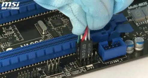
The majority of other manufacturers’ motherboards, including those from MSI, feature a JFP1 connector, allowing quick connecting of front panel wires like power, reset, and speaker.
Because they make it simpler to correctly and quickly link up your PC’s front panel without running the danger of making erroneous polarity connections, MSI employs split connectors, which are known to be more dependable than the single-pin design.
This connector is provided in two parts on some MSI motherboards, allowing you to take cable management into account when installing tall front-panel connectors.
If you encounter difficulties during installation, keep in mind that you can frequently remove the black plastic cable shroud from taller connectors and wrap the cable directly around the prongs to make it fit snugly below them.
Wrapping Up:
Finally, the JFP1 header on my motherboard plays a crucial role in linking up the front panel parts of my computer case. It’s the key to unlocking the full potential of those buttons, LEDs, and audio ports on the front panel. When I get the JFP1 header correctly mounted and connected, it’s like opening the door to a world of functionality and convenience. Now, all those features are at my fingertips, thanks to the proper setup of the JFP1 header.
FAQs:
Q1. What happens to JFP1 cables?
JFP1 is short for “Jumper Front Panel 1.” The motherboard and those connectors on the front panel of the computer casing are linked by connectors. Typically, these ports are located close to the motherboard’s front. The front panel of the chassis has buttons for the power and reset of the computer.
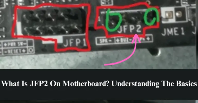
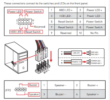
Q2. What is a JFP2 connector?
JFP2 headers are commonly located on the front panel of motherboards with pins. Its primary functions include:
- Providing the device with electricity.
- Performing a device reset.
- Managing the unit’s LED lights.
On some motherboards, a speaker or buzzer jack with the designation JFP2 may be present.
Q3. What is JTPM1 on a motherboard?
TPM Module Connector: JTPM1. TPM (Trusted Platform Module) connections are made using this connector. For more information and applications, please consult the TPM security platform documentation.
Q4. How can I plug something into JFP1?
The front panel components that must be attached to the JFP1 header should be identified. These elements might include the speaker (if present), power button, reset button, power LED, HDD LED, and power button LED.
Q5. Do JFP1 cables need to be used?
Yes. The connectors on the motherboard serve the purpose of instructing the computer to turn on and operate. Some motherboards that are used for testing and other purposes may feature a “Start” and “Reset” buttons on the motherboard itself to make it easier to operate.
Read Also:
- How To Remove Motherboard Standoffs? Removing Standoffs Like a Pro
- How To Dual Monitor With GPU And Motherboard? A Detail Guide 2023
- What Motherboards Are Compatible With Ryzen 7 5800x? | 8 Best Motherboard For Ryzen 2023
- Can A Motherboard Bottleneck the GPU? Reasons & Fixes 2023
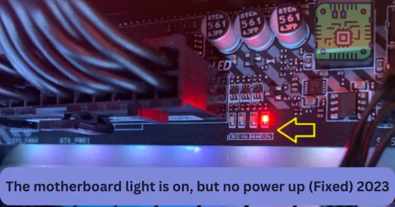
- What Is Orange Light On Motherboard And How To Fix Issue?
References:
- https://www.reddit.com/r/buildapc/comments/13whhw5/whats_the_difference_between_jfp1_and_jrgb1_on/
- https://forums.tomshardware.com/threads/wires-wont-fit-to-jfp1-connectors.402273/
- https://ubuntuforums.org/archive/index.php/t-1364114.html